Memory map
The board can be run in three difenent modes:
| Run mode |
: |
Normal stand-alone mode |
| Debug mode |
: |
Use with software debugger |
| Programming mode |
: |
In-circuit-Programming for the flash |
By using the three modes, you can develop software quite comfortably, program the flash memory via the serial interface and use the board as stand-alone board without a PC. Because the used controller can only address 64kB of ROM, half of the flash (29F010) would not be used. For the debug mode a monitor program is needed, which must also be placed in the flash and would reduce the usable memory. By using an additional portpin, the address line A16 is emulated and (almost) the entire flash can be used.
Standard mode
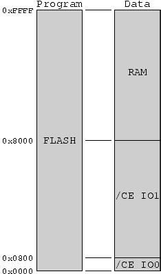 |
This mode is used, when the program developement has been completed. After startup the program in the flash is startet from address 0x00000. Address line A16 has a low level. because the control line D/R (Debug/Run) has a low level. 64kB of ROM is available in the flash, from address 0x00000 up to 0x0FFFF. In the range from 0x8000 to 0xFFFF 32kB of RAM can be used. Additionally nine general purpose chip-select-lines can be used in the I/O-range. /CE0 to /CE7 are in the data memory from 0x0000 to 0x0007, /CE_IO1 can be used for additional memory-mapped-I/O and is low in the range between 0x0800 to 0x7FFF (this has been published erroneously in the Elektor, where the address range startet at 0x0008). |
Debug mode
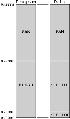 |
In this mode the board can be used together with the source-level-debugger SLD51 from the development enviroment μC/51 of
Wickenhäuser. With this the program is downloaded to RAM via the serial interface and can be stepped-through and tested. The operating system, which makes this possible, is called OS552 and lies in the flash in the range from 0x10000 to 0x17FFF. This range is mirrored for the controller in the range from 0x0000 to 0x7FFF. This upper 32k of the flash cannot be used, because the RAM is located here. The memory-mapped-I/O is on the same addresses as in the run mode, so it can be tested too. |
Programming mode
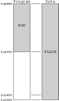 |
The final mode is the programming mode, in which the flash memory can be reprogrammed. Because it is not possible to run a program from the flash and simultaneously erase and reprogram the flash, the program has to be run from RAM. For this in the debug mode the bootloader is copied from flash to RAM and the board is switched to the programming mode. Now the RAM becomes the program memory and the flash the data memory. To prevent problems with the memory-mapped-I/O, these are disabled in the programming mode. |
|


