|
 |

| Main page | Projects | Electronics | Building furniture | Recipies | Corgies | About me |
| Electronics | 80c552 µC-board | Mainboard | Preamp | Power amplifier | Making PCBs | Tools |
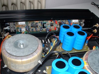
Power amplifier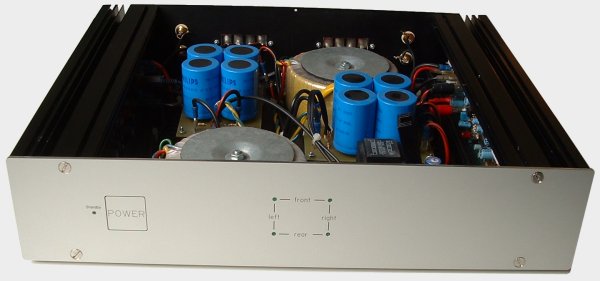 The image above shows my power amplifier, which consists of two kits K4005 by Velleman. Both have a power of 2x100W at 4 ohms. Features like short-circuit-protection and speaker transient suppression are also built in. The heatsink is also the PCB-housing. The housing of the power amplifier is built from both heatsinks and the panel set HB430936, which can also be ordered from Velleman. This results in a very stabil housing. The pover supply consists of a toroidal core transformer and four electrolitical capacitors with 10.000µF/63V for each power amplifier. (schematic, copper, components). The pictures below show the capacitor PCB. 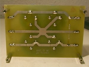 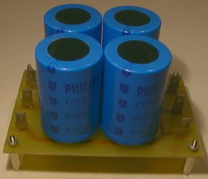
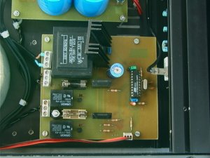
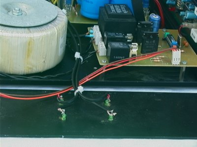
To switch the power amplifier on and of with a pushbutton, I designed a small microcontroller circuit, which reads the pushbutton and controls two solid-state-relays. It seems a bit overkill to use a microcontroller for such a simple task, but this solution was the simplest and the cheapest. The problem is, that the pushbutton must be debounced, so the 16A housefuse is not killed when both transformers are switched on and off a few times in succession. Furthermore a flipflop is required, which switches into a defined state after power-up. Because the microcontroller only costs about €2,50, I decided to use this solution. The debouncing of the pushbutton is now done by software. The front panel was milled bei Schaeffer in Berlin, like the one for the preamplifier (front panel and power button). The mechanism for the button is the same as with the preamplifier. MicrocontrollerThe schematic for the microcontroller circuit, which controls the amplifier, can be downloaded here. At the left part of the schematic is the power supply of the control, which consists of a rectifier, capacitor and a voltage regulator. Beneath the power supply are both solid-state-relays, that switch on the toroidal core transformers. To limit the switch-on-current, two NTCs are places in series with the transformers and are short-circuited after about one second. In the right of the schematic is the microcontroller, an AT89C2051 from Atmel. The pushbutton and the LED in the front panel are connected to J5. The jumper at pin 11 controlles the power-on behaviour of the amplifier: either the amplifier is off when the power is plugged in or the amplifier is switched on, which can be used when the amplifier is connector to the 230V-output of the preamplifier. The PCB-layout can be downloaded (copper and components) More pictures
|