|
 |

| Main page | Projects | Electronics | Building furniture | Recipies | Corgies | About me |
| Electronics | 80c552 µC-board | Mainboard | Preamp | Power amplifier | Making PCBs | Tools |
Schematics
Construction
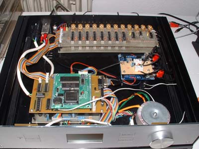
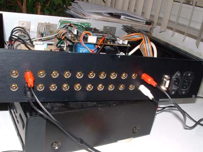
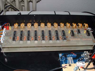
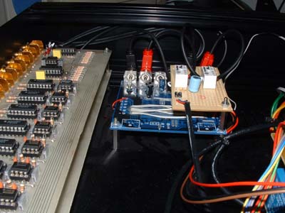
Practical construction
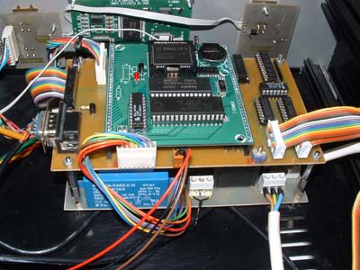
Front panel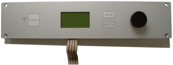 The picture above shows the front panel. As you can imagine, the power button is used to switch the preamp on and off. The LED next to the button shows the standby-state of the amplifier or by blinking the reception of commands from the remote control. In the middle of the front panel is the graphic LC-display. On the right half of the panel are the controls of the preamp. The main element is the large turning knob, which is connected to a rotary encoder. It is also possible to press the knob to control some special functions. With the pushbuttons Menu and Enter the user can select from several menus on the display. Mechanical contruction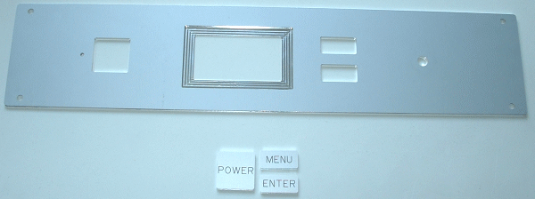 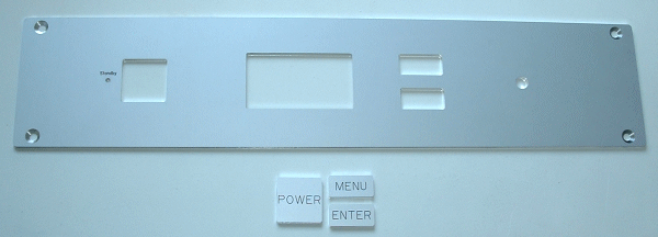 The front panel was milled by Schaeffer Apparatebau. From their homepage you can download the Front panel designer. This program allows you to design a front panel and to send those data to a CNC milling machine. The files I created can be downloaded here. The pictures show the front and back side of the front panel. 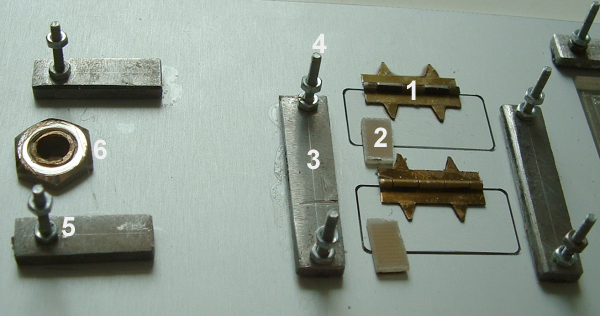 The pushbuttons are connected to the front panel with small hinges (from a cigar box, 1). To prevent the pushbuttons from falling out of the panel, I glued small pieces of PCB material behind them (2), so they can only flap inwards. For the actual pushbuttons I made some small PCBs, which are screwed behind the panel. Since I didn't want any holes in the front panel to mount the PCBs, I glued small metal pieces to the back of the front panel (3), in which the screws are mounted (4). For mounting the PCB with the rotary encoder, I used the same technique (5). Additionally there is a lead-through for the axis between them (6). 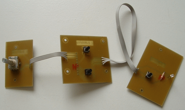 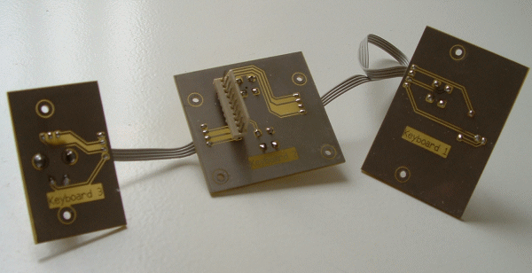 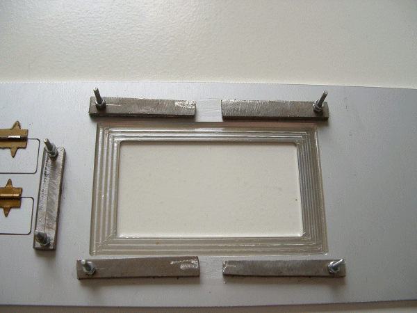 ResultBelow you can see the result of this mounting technique. "Keyboard 3" is the PCB with the rotary encoder, next to it is the PCB with the two pushbuttons ("Keyboard 2"). Additionally on this PCB is the connector for connecting the front panel with the controller. To the right you see the counting of the LC-display, which is the same as for the PCBs with the pushbuttons. The bottom picture shows the PCB with the power-pushbutton and the standy-LED ("Keyboard 3"). 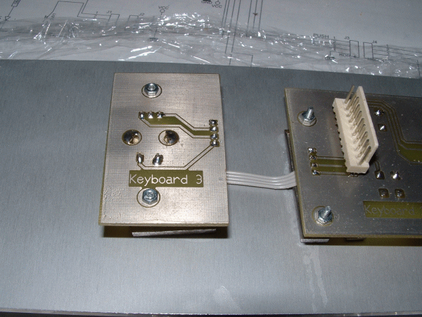 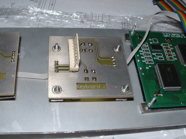 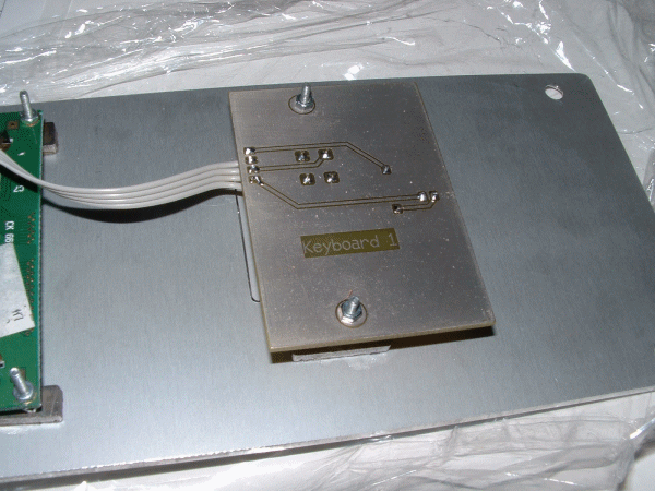
A few more pictures
|