 |
 |

| Main page | Projects | Electronics | Building furniture | Recipies | Corgies | About me |
| Electronics | 80c552 µC-board | Mainboard | Preamp | Power amplifier | Making PCBs | Tools |
Schematics
Construction
Schematics80C552-microcontrollerBecause the control amplifier and the equalizer are controlled by I2C-signals, the easiest way was to choose a controller which already has that interface. The choice between the 80C552 and the 80C562 was decided in favor of the first one, because it has two additional 8-bit-ports, so fewer latches are needed. Audio inputsFor selecting the audio inputs, I choose a part of an Elektor-project. In this project (I believe it was called audio-center, which was printed at the end of the eighties) eight audio inputs are switched to a line out and a tape out with two multiplexers. The trick with this circuit was, that the distortion of the signal was minimal because the voltage over the FETs in the multiplexers was always 0V. Since the PCB layout was also very good (high channel separation) I used these PCBs. I replaced the second part of the project, the volume control, by another circuit. 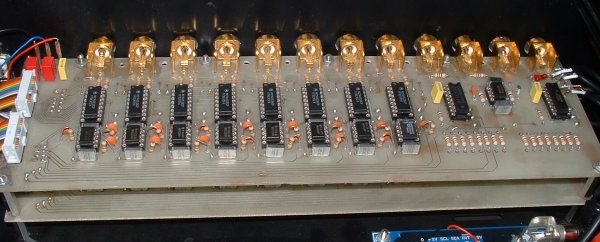
Control amplifierFor the control amplifier I also used an Elektor project, the I2C control amplifier. Here two ICs from Philips, TEA6330 and TEA6360, are the control elements. The circuit is mostly the same as the aplication notes from Philips. The TEA6330 is a control amplifier which is operated by I2C. The volume for the left and right channel can be changed independantly, which allowes a balance control. With the fader the volume can be changed from back to front. The 5-band-equalizer is made of the TEA6360 and a lot of SMD resistors and capacitors. This IC too is controlled by I2C. MicrocontrollerFor controlling all functions of the amplifier, I (of course) use the 80C552-µC board, which I developed for this purpose. The interface to the remaining hardware is made by the mainboard Power supply
Switching noises suppressorTo suppress noises from switching on and off, two relais have been placed between the control amplifier and the output. This short-circuits the output until a few seconds after power-on and at power-off directly to ground. Because the relais is not directly in the signal path, they don't deteriorate the signal quality. I build this circuit on a small experimental board, which is mounted directly above the control amplifier. |
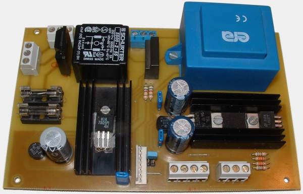 An additional part of the amplifier is the power supply. This consists mainly of three linear voltage regulators, which generate an asymetric voltage of 5V and a symetric voltage of plus and minus 7,5V. For the 5V-rail a small transformer is mounted directly on the PCB, which gets its power over a net filter (TR1). This makes sure that pollution on the mains, which comes from fluorescent lamps or dimmers, cannot reach the controller, which is a bit allergic to this. As long as the preamp is connected to the mains, the controller is supplied with power, even when the amplifier is switched off. I estimate that the standby power is about 1W. This can be reduced by switching off unused parts of the controller PCB, but at this point in time I'm just trying to make the preamp work. The transformer for the symetric 7,5V is a toriodal core transformer, which is mounted next to the power supply PCB in the housing. It is switched on by S2 via K3. The second solid-state-relais switches a power output, which is connected to a power connector on the back of the housing. It can be used e.g. for a power amp. Of course, there is also a